

Construction, Structural, Uncategorized
Tower Crane Lateral Support: How We Design, Check, and Install Safe Tie-ins on High-Rise Sites
Nov
Design brief and philosophy
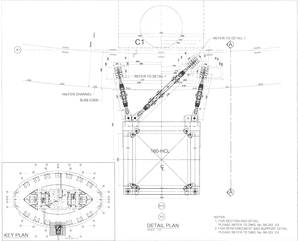
For the referenced scheme (Liebherr 500 HC family), the manufacturer’s reactions were adopted directly into the tie connection design. The critical horizontal tie load was taken as 729 kN acting at the J-bar/tie axis, with combinations checked for both tension and shear. The calculations were developed against UK steelwork and concrete guidance with explicit safety factors to BS/PCI practice.
Referenced standards & methods (from the document):
- BS 5950 (structural use of steel) and BS 8110 practice for RC design checks.
- SCI 212 for moment connections in steelwork.
- PCI Handbook design provisions for stud groups/pull-out and shear cone behavior.
- Analysis/drafting via AutoCAD plus calculation sheets.
Tie connection hardware & materials
The typical bracket detail uses M36 bolts, Grade 10.9, into a 40 mm thick steel plate, fixed back to a reinforced concrete slab edge/beam designed for the local punching and bearing. Concrete strength and rebar grades are set to match the host slab (e.g., high-strength concrete around C60 with Grade 460 reinforcement in the sample pack). The document increases bolt size to M36 and limits concrete bearing to 15 MPa at the interface—conservative moves that improve robustness and construction tolerance.
What we check (engineer’s checklist)
- Bolt group
- Combined tension + shear per SCI/BS.
- Bearing of steel plate and bearing of concrete at sleeves/anchors.
- Pull-out / pry-out of anchors; stud-group shear cone capacity (PCI figures and equations are included in the pack).
- Bracket plate & welds
- Plate bending under eccentric tie load; weld throat sizing and local stiffeners as required.
- RC host slab/edge beam
- Local bending and punching shear where the tie resolves into the slab.
- Minimum slab thickness / stud embedment to avoid thin-plate cone failures (PCI 45° cone and thin-member cases are shown).
- Load factors & combinations
- Manufacturer ultimate tie force × 1.6–1.7 (BSI/PCI factors in the document), plus construction live loads where relevant.
- Geometry & sequencing
- Tie geometry drawings show adapter arms and bar pin connections that must be temporarily unlockedat specific levels during climbs—called out clearly on the elevations. Strict adherence prevents unintended restraint during slewing or jacking.
Typical details you’ll see on our drawings
- Plan & section of the tie bracket with bolt sleeves, non-shrink grout pockets, Halfen channels at slab edges, and balcony slab reinforcement local to the bracket.
- Elevation of tie-in levels from the crane base to the highest tie, including wind-state notes (e.g., out-of-service/parking angles) and the lever arm for mast moments.
- Rebar add-ins around sleeves and at slab edges to close the shear cone and distribute loads.
Step-by-step installation & QA
- Pre-works: Survey tie coordinates; mark slab edge; scan for rebar/services. Review RAMS and lift plan.
- Core/sleeve and fixings: Drill to designed embedment; clean holes; place sleeves; grout with specified non-shrink; cure per datasheet.
- Bracket fit-up: Offer the plate; install M36 Grade 10.9 fasteners to torque; install spacers/shims to maintain geometry.
- Rebar/local RC works: Place additional reinforcement and patch pours around channels/sleeves as detailed.
- Tie bar connection: Connect to mast adaptor; check pin locks and safety clips; verify slewing clearances. Follow the elevation notes where specific connections must be unlocked during climbs.
- Inspection & sign-off: Bolt ID/grade verification, torque logs, grout cube/wedge tests if specified, as-built survey, ITP hold points for Temporary Works Coordinator.
Common pitfalls we design out
- Underestimating tie force by using service instead of ultimate reactions—this pack explicitly uses 729 kNultimate as the governing case.
- Ignoring slab punching around sleeves—PCI cone checks and BS punching checks are run; local thickening/rebar added where needed.
- Edge distance too small for stud groups—drawings show set-outs that keep effective cone areas intact.
- Climb sequencing—notes call for unlocking tie pins at specific levels during climbing to avoid binding.
Deliverables you get from us
- Tie-in calculation pack: loads, factors, bolt/slab checks, and connection capacity summaries.
- GA + details: plan, sections, elevations, reinforcement plans, and a level-by-level tie schedule.
- RAMS + ITP tailored for London sites (tight logistics, balcony edges, public interfaces).
Ready to plan your crane ties?
As a design-and-build structural team, we package temporary works with permanent works, so slab edges, balcony geometry, and tie brackets are coordinated from day one. Share your crane model, freestanding height, and target tie levels—we’ll return a coordinated tie schedule, drawings, and a sign-off checklist aligned with your programme.