

RC Frame, Structural
Structural Design of Generator Lifting Steel Beam for Mechanical Rooms
Nov
1. Purpose of the Generator Lifting Steel Beam
According to the report, the lifting system was designed specifically for the location bounded by Gridlines H–J/21–22.
The key objectives were:
✔ 1. Provide a permanent lifting point inside the mechanical room.
Generators can weigh up to 15,155 kg (148.64 kN), and the lifting beam needed to resist a 20 kN crane load, bringing the total moving load to approximately 179 kN (as shown on page 5 of the report) .
✔ 2. Enable horizontal movement of the generator.
The beam was aligned so a chain block or trolley could run along its length, allowing the generator to be lifted at one point and slid to another for maintenance or replacement.
✔ 3. Avoid the need for temporary lifting frames or external cranes.
Mechanical rooms are often internal with limited access. This beam became the building’s “internal crane”.
✔ 4. Ensure long-term safety under repeated lifting operations.
This required:
- Extensive load calculation,
- STAAD Pro analysis,
- Design of anchors, bolts, and suspending angles,
- Verification of supporting reinforced concrete beams.
All these elements appear throughout the detailed calculation sheets () .
2. The Structural Design of the Lifting Beam
Steel Section Specification
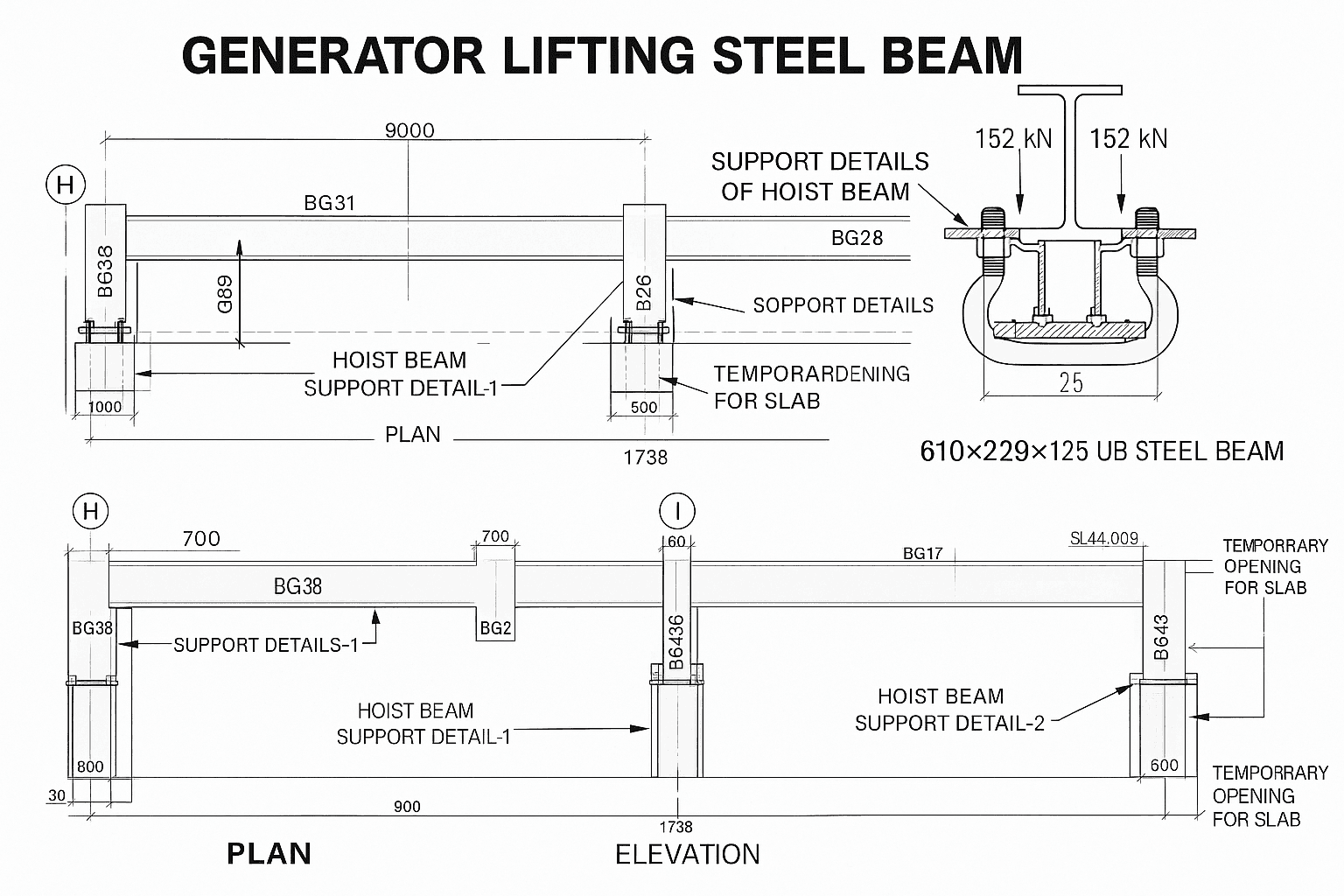
The beam used was a 610×229×125 UB steel beam, as shown on the detailed drawings () . This section was selected to meet the combined bending, shear, and flange-local-bending forces.
Load Assumptions Used in Design
From the load calculation sheet (page 5) :
| Load Type | Value |
|---|---|
| Dead Load (generator self-weight) | 148.64 kN |
| Live Load (lifting crane load) | 20 kN |
| Dynamic Effect | 50% increase |
| Total Moving Load | 178.6 kN |
The maximum reaction at support reached 303.755 kN after factoring () .
Local Flange Bending
The wheel loads of the lifting trolley were considered using only two wheels for conservative design (page 3).
The resulting flange stress was 188 N/mm², safely below the design strength of 265 N/mm², per BS5950 .
Bolts, Hangers & Anchors
The steel beam was supported by:
- 4 steel angles (60×60×6 mm)
- 16 bolts (grade 8.8)
- Hilti chemical anchors, with detailed tables (pages 21–24) specifying anchor strength and setting depths.
The shear and tension capacities of all bolts and hangers are listed on , showing all capacities exceed the factored reactions by a safe margin .
Supporting Reinforced Concrete Beams
The RC beams BG106, BG38, and BG45 were checked for adequacy ():
- Steel reinforcement was reviewed.
- Additional links (4T12 @180) were recommended to increase shear capacity.
- STAAD Pro models were run to confirm deflection and moment capacities ().
3. How the Beam Created a Full In-Room Lifting System
A. Horizontal Movement
The beam spans across the mechanical room (page 17–18) where the plan and elevation drawings show:
- Beam installed at high level,
- Supported on two reinforced columns,
- Aligned to allow trolley travel from one end to the other.
This transforms the beam into a mini overhead-gantry system, fully capable of shifting a generator laterally.
B. Vertical Lifting
The top flange of the UB beam carries the trolley which connects to:
- Chain block,
- Hoist motor (if used),
- Hooks/slings.
This allows lifting from floor level to suspended level safely.
C. Room-Wide Accessibility
By positioning the beam across the generator’s footprint, engineers can:
- Pull the generator out of its housing,
- Move it along the beam to an open area,
- Lower it onto transportation skids/bearers.
4. How This Engineering Solution Solved Major Maintenance Problems
Mechanical rooms traditionally suffer from:
❌ No space for temporary lifting frames
The beam eliminates the need for mobile gantries.
❌ Difficult generator replacement
Generators often fail after years of operation. Without a built-in lifting system, the only option is breaking walls or roofs.
❌ Safety risks
Temporary lifting systems can fail due to improper installation.
❌ High operational costs
Hiring external cranes or dismantling building fabric is extremely expensive.
✔ The New Lifting Beam Solved All These Problems Permanently
1. Safe Replacement of Generators
The mechanical team can now remove the generator by simply lifting and shifting it along the beam.
2. No Building Alteration Required
The building remains intact for the entire life cycle of the equipment.
3. Reduced Maintenance Time
Routine inspection, oil tank removal, alternator replacement—everything is now quicker.
4. Guaranteed Engineering Reliability
The beam is designed to withstand:
- High load factors,
- Dynamic effects,
- Repeated lifting cycles,
- Long-term fatigue conditions.
5. Cost Savings for the Client
Over the building’s service life, this design avoids hundreds of thousands of pounds in future intervention costs.
Conclusion
The “Generator Lifting Steel Beam” is a prime example of engineering foresight.
By integrating a permanent lifting solution inside the mechanical room, the designers eliminated future access challenges and ensured long-term maintainability of one of the building’s key life-safety assets.
This solution demonstrates how advanced structural design, rigorous calculation, and precise coordination can dramatically improve operational efficiency inside complex buildings.