

Construction, RC Frame, Structural
Tower Crane Support Beams Explained: How Internal Crane Supports Really Work
Nov
1. What do we mean by “tower crane support”?
A tower crane support system is everything that transfers crane forces safely into the permanent structure. It usually includes:
- The crane mast – a lattice tower that carries vertical load and bending.
- The climbing frame / collar – clamps the mast to the building so the crane can climb as floors go up.
- Support beams or grillages – often deep steel beams spanning between core walls or columns.
- Anchors and embedded plates – bolts and welded plates cast into concrete walls or slabs.
- The supporting walls or cores – reinforced concrete walls that ultimately take the loads down to the foundations.
If any part of this chain is weak, the whole system is at risk. That’s why the supporting beams and their connections are treated like a critical structure within the building.
2. Example: internal tower crane on steel beams between concrete walls
In the sample calculations, the crane is supported by a heavy rolled steel beam (HE section) that spans between two opposite reinforced-concrete walls inside an elevator shaft.
The concept is:
- The climbing frame of the crane bears on a saddle beam assembly.
- This saddle beam is welded and bolted to the main supporting beam.
- The supporting beam is fixed to base plates at each end.
- The base plates are anchored into the concrete walls using groups of high-strength anchor bolts cast into the wall.
- The walls are detailed with additional reinforcement so they can resist local bearing and global bending from the crane.
This arrangement lets the crane stand inside the building footprint and climb upward as the core is constructed.
3. Design information from the crane manufacturer
The first step is to obtain accurate reaction forces from the crane supplier. In the example, manufacturer’s data at the upper climbing frame gives:
- Maximum design overturning moment at the climbing frame,
M ≈ 8,134 kNm - Maximum vertical reaction (compression in mast),
V ≈ 876 kN - Maximum horizontal shear (due to slewing and wind),
H ≈ 168 kN
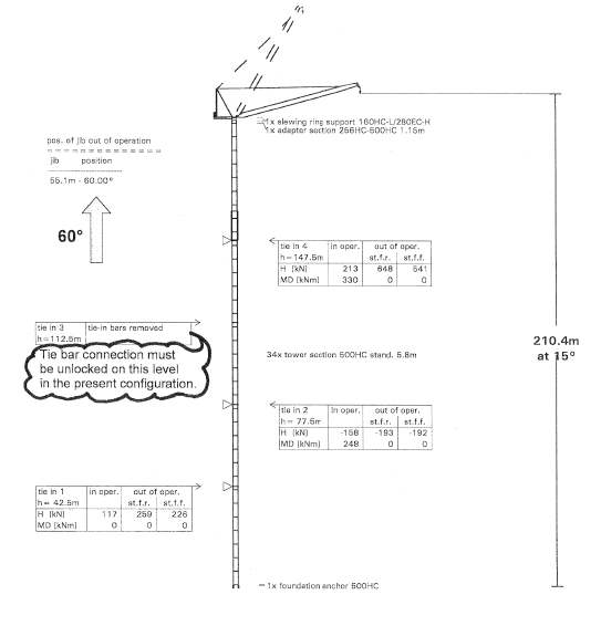
The vertical spacing between consecutive support levels is 14 m, so the total horizontal shear over that height is shared by the various support levels. For one level, the beam must resist horizontal reactions on the order of ~187 kN and vertical reactions around ~219 kN at each bearing point.
These values are already factored for dynamic and wind effects according to the crane manufacturer’s own design standard.
4. Design philosophy for the tower crane support beam
The calculation document sets a clear philosophy:
- Check the beam for two key directions:
- Horizontal forces perpendicular to the beam axis (out-of-plane push/pull on the walls).
- Horizontal forces parallel to the beam axis (along the length of the beam).
- Verify connection stability between:
- Crane climbing frame and support beam.
- Support beam and concrete walls via base plates and anchors.
- Check the reinforced-concrete walls for:
- Local bearing under the base plates.
- Global bending and shear due to the crane forces.
Design is carried out to BS 5950-1:2000 for the steelwork and connections, using ETABS structural software to analyse the steel beam and to extract internal forces and deflections.
5. Materials and key components
From the example project:
- Concrete:
- Characteristic cube strength fck = 60 MPa (high-strength core concrete).
- Steel beam:
- Grade S355 structural steel.
- Anchor bolts:
- Grade 8.8 high-strength bolts, arranged in two bolt groups at each end of the beam.
- Welding:
- Site and shop welds designed to E60 electrode classification.
These choices reflect the need to handle very high concentrated loads in a compact space.
6. How the steel support beam works
6.1 Global beam behaviour
The support beam behaves like a simply-supported or continuous deep girder between two concrete walls:
- The crane loads are applied at locations along the beam via the saddle frame.
- ETABS is used to model the beam, apply the vertical and horizontal loads, and calculate:
- Maximum bending moments.
- Shear forces.
- Deflections.
The beam section is then checked for:
- Bending capacity (M<sub>Ed</sub> ≤ M<sub>Rd</sub>).
- Shear capacity.
- Combined bending and shear.
- Deflection limits, to keep crane alignment within tolerance.
6.2 Connection of beam to concrete walls
At each end, the beam sits on a base plate anchored to the wall with multiple M24 anchors. The design checks include:
- Bearing stress on concrete under the base plate (ensuring σ<sub>bearing</sub> ≤ f<sub>cu,allow</sub>).
- Bolt shear from horizontal loads.
- Bolt tension from overturning moments.
- Combined shear + tension in each bolt (per BS 5950).
- Adequate edge distances and anchor spacing to avoid splitting or cone failure in the concrete.
The sketches in Appendix C show:
- Bolt group 1 and group 2, each with 4–6 M24 bolts.
- A stiffener plate under the crane mast to prevent local web buckling of the beam.
- Saddle beam details welded to the main support beam.
7. Concrete wall checks
The reinforced concrete wall is not just a passive support – it is actively designed to carry the bending and shear from the crane.
From the sample wall check:
- Wall thickness ≈ 370 mm.
- Additional vertical and horizontal reinforcement is compared with the required steel for:
- Maximum out-of-plane moment M<sub>x</sub> ≈ 170 kNm per metre.
- Maximum in-plane moment M<sub>y</sub> ≈ 130 kNm per metre.
The result: existing plus additional reinforcement is sufficient to carry the factored loads, so no ultimate load combination modification is required.
This step is crucial – there is no point designing a perfect steel beam if the concrete wall behind it crushes or cracks.
8. Construction sequence and practical considerations
In real projects, tower crane support beams are as much about buildability as pure calculations.
Typical sequence:
- Cast the core walls to a given level, leaving:
- Box-outs and sleeves for the anchor bolts.
- Recesses where base plates will sit.
- Install the anchor bolts and plates, usually with a template to maintain tolerance.
- Position and weld the support beam assembly complete with saddle beams and stiffeners.
- Erect the crane mast and connect it to the climbing frame and saddle beams.
- As the building climbs:
- Either jack the crane and reuse higher support levels, or
- Install new support beams at higher floors and disconnect the lower level once the new one is active.
Key site issues:
- Tolerances – if levels are out, the crane mast can lean, causing extra bending.
- Temporary works – propping may be needed until concrete reaches full strength.
- Access & logistics – these beams are heavy; lifting points, crane capacity and installation sequence must be planned.
9. Good practice in tower crane support design
From an engineering and risk-management point of view, the following are non-negotiable:
- Use manufacturer data – never guess crane reactions.
- Apply correct partial factors – include wind, dynamic effects, and out-of-service conditions.
- Check all load paths – from mast to saddle, saddle to beam, beam to bolts, bolts to concrete, concrete to foundations.
- Limit deflections – to maintain crane plumb and avoid tracking problems on the slewing ring.
- Consider progressive collapse – where possible, design for robustness if one bolt or local component fails.
- Coordinate with permanent design – ensure the crane support does not clash with cores, lift shafts or architectural openings.
10. Why clients should care
For developers and contractors, a well-designed tower crane support system delivers:
- Safety – reducing the risk of catastrophic failure.
- Programme certainty – minimal downtime due to crane issues.
- Cost efficiency – optimised steel tonnage and re-use of support levels where possible.
- Futureproofing – supports tied into the permanent structure with minimal rework once the crane is dismantled.
A properly engineered support beam is, quite literally, what holds your construction programme in the air.