

Cladding, Structural
Engineering a State-of-the-Art Support Beam for a Massive Aluminium & Glass Architectural Canopy
Nov
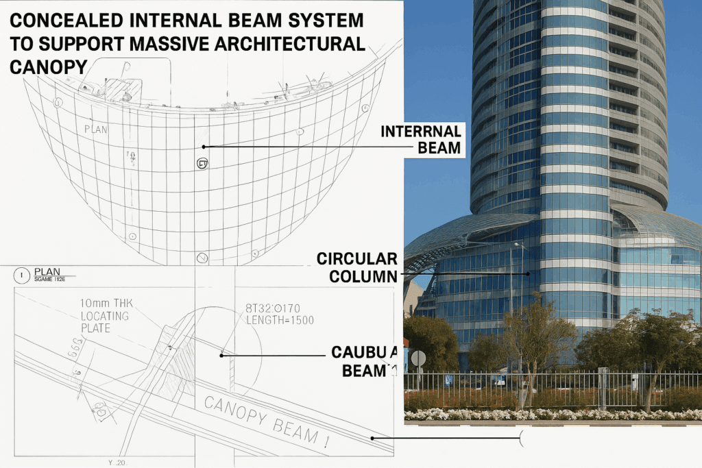
Understanding the Challenge: How Do You Support a Heavy Canopy Inside a Column?
The architectural canopy was designed as a complex curved glass and aluminium surface, hung from multiple discreet points. Two of these major reaction points—Supports E & G—were located exactly where no traditional steel support could be installed: inside the concrete circular columns.
The challenges included:
1. No external brackets permitted
The architects required a clean, uninterrupted external finish. No visible brackets or projections could be attached to the column.
2. High concentrated loads
Each support carried massive forces, including:
- 150 kN vertical load (downwards)
- 30 kN uplift
- 15 kN axial forces
(as per the design load diagram on page 7 of the report)
3. Significant torsional moment
Because the load was eccentric—1.2 m away from the beam centreline—the design needed to resist substantial torsional forces transmitted into the column (calculated on page 8) .
4. Limited pocket size inside the column
The entire beam and connection system had to fit inside a very narrow pocket without cutting or weakening the column’s reinforcement.
5. Durability, safety and zero movement
The canopy’s precision meant millimetre-accurate positioning. Any deflection would affect glass alignment.
The solution required a high-capacity, torsion-resistant steel beam system, installed entirely within the column’s core.
Our Engineering Solution: A Fully Integrated Internal Beam System
Based on the structural design philosophy defined in the report’s General Section , our solution relied on three core engineering principles:
1. A Customised Square Hollow Section (SHS) Beam Hidden Inside the Column
The design adopts a high-capacity square hollow section (SHS) steel beam because:
- SHS resists torsion more efficiently than I-beams.
- SHS allows a clean connection to plates and bolts.
- Its geometry fits within the curved concrete column pocket.
This beam acts as the primary structural member transferring canopy forces into the concrete column.
2. Full End-Plate & Bolt Connection Into the Concrete Column
The design (referenced in the end-plate calculations p.11–12) uses:
- 20 mm end plates
- High-strength T32 grade reinforcement bars
- Full penetration butt welds
- Bolted anchor groups designed to carry combined bending & tension
This connection ensures the beam becomes a fixed structural element inside the column, resisting:
- Vertical shear
- Torsion
- Bending
- Axial forces
The bolt and plate system was checked against multiple failure modes (Mode 1, 2 and 3 checks on page 12) and found fully compliant .
3. Transfer of Loads Safely Into the Concrete Column
The embedment length for the anchor bars was designed at 1400 mm (p.13) to ensure perfect load transfer into the column’s reinforced concrete mass .
Removing the back portion of concrete was part of the engineering strategy—this allowed insertion of the beam without compromising column stability.
The STADD analysis (pages 15–18) verified all load combinations and reactions, showing the beam performance under:
- UDL
- Point loads
- Combination moments
- Torsional stresses
All stresses were found within allowable limits (p.8 summary) .
How This Beam Transformed the Canopy Installation
✓ The canopy load was safely anchored to the building core
Instead of relying on external brackets, the load is now transferred inside the column, creating a permanent solid support point.
✓ The solution allowed a heavy glass canopy to “float” visually
Because the beam was hidden, the architecture achieved a seamless finish.
✓ The internal pocket support problem was solved
The building’s circular columns originally had no built-in support zones.
This engineered beam created a new internal structural pocket, capable of carrying:
- 150 kN vertical
- 30 kN uplift
- 15 kN axial
- 88–130 kN torsional shear reactions
(all verified within the design calculations on pages 8–11) .
✓ It met all design codes
The design adhered to:
- BS 5950-1:2000 Steel Design Standard
- STAAD Pro structural modelling
- Reinforced concrete anchorage requirements
✓ It preserved the architectural intent
No visible changes to column geometry.
No impact on the façade.
100% concealed engineering.
A State-of-the-Art Structural Achievement
This project demonstrates how high-end structural engineering makes world-class architecture possible.
By designing a compact yet incredibly strong internal beam system, we were able to:
- Support a massive curved aluminium-and-glass canopy
- Transfer high forces into a column without visual impact
- Solve a complex pocket support challenge
- Create a permanent, highly durable structural solution
- Maintain the building’s aesthetics and integrity
The engineering was not just functional—it was architectural, invisible, and state-of-the-art.