

Construction, RC Frame
Structural Design of Temporary Hoist Platforms
Nov
1. Purpose and Structural Role
The hoist platform carries significant vertical and horizontal loads. Its frame transfers forces from the lift cage to the building structure and down to the foundation. The system includes base plates, anchors, and tie beams that resist both sway and wind action.
2. Design Standards
The design follows BS 5950 and BS 8110, the key British standards for steel and concrete structures. These codes define strength limits, safety factors, and detailing rules. The design also refers to the Blue Book capacity tables for verifying steel member performance.
3. Design Philosophy
The platform sits on a 4.5 m × 4.5 m × 0.4 m reinforced concrete base slab.
Propping extends from the foundation to the basement, spreading the load safely to the ground.
The slab is designed for a bearing pressure of 150 kPa.
Lateral ties connect to the building every 7.5 m, ensuring minimal movement and stability during lift operation.
4. Material Specification
- Steel grade S275 is used for columns and braces.
- Bolts are grade 8.8, typically M20–M24.
- Full penetration welds are applied at main joints for maximum strength.
All materials comply with standard UK structural testing and traceability requirements.
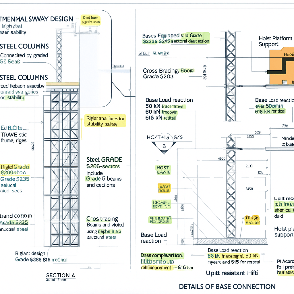
5. Frame and Bracing System
The frame is a truss structure of rectangular and H-section members. Cross bracing increases lateral stiffness.
Each tie level is engineered to resist 80 kN horizontal and 56 kN perpendicular loads, taken from hoist manufacturer data.
Anchor bolts and gusset plates transfer these forces into the reinforced concrete base.
6. Foundation and Base Reactions
The base slab carries combined vertical and horizontal reactions:
- Vertical load: 618 kN (mast + cage + accessories)
- Horizontal load: 46 kN total
Punching shear and bending checks confirm compliance within BS 8110 limits.
The foundation ensures even stress distribution and no differential settlement.
7. Installation and Safety
Accurate surveying of anchor bolt locations is essential before fabrication.
After installation, all welds are checked by non-destructive testing (NDT).
Bolt torque is verified to avoid joint slippage under load.
Temporary bracing must remain in position until all ties and concrete cures are complete.
8. The Pega Hoist Example
The project uses the Pega P3240 TD HS hoist system.
It lifts up to 3,170 kg, at speeds of 100 m/min, reaching 150 m height.
During erection, engineers control moments up to 82.8 kNm at the base, ensuring the frame remains stable even before the first tie is fixed.
Conclusion
A temporary hoist platform is more than scaffolding — it’s a structural system.
Every bolt, brace, and weld follows a clear load path designed to resist movement, bending, and uplift.
By combining code-based design, material control, and field verification, engineers ensure the safe operation of vertical transport systems throughout construction.